Components Overview
The PCB design of the Arduino UNO uses SMD (Surface Mount Device) components. I entered the SMD world years ago when I dug into Arduino PCB design while I was a part of a team redesigning a DIY clone for Arduino UNO.
Integrated circuits use standardized packages, and there are families for packages.
The dimensions of many SMD resistors, capacitors, and LEDs are indicated by package codes such as the following:
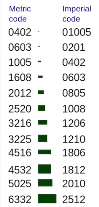
SMD package code for discrete components such as resistors, capacitors, and inductors. Image courtesy of Wikimedia.
Most packages are generic and can be used for different parts with different functionality. The SOT-223 package, for example, can contain a transistor or a regulator.
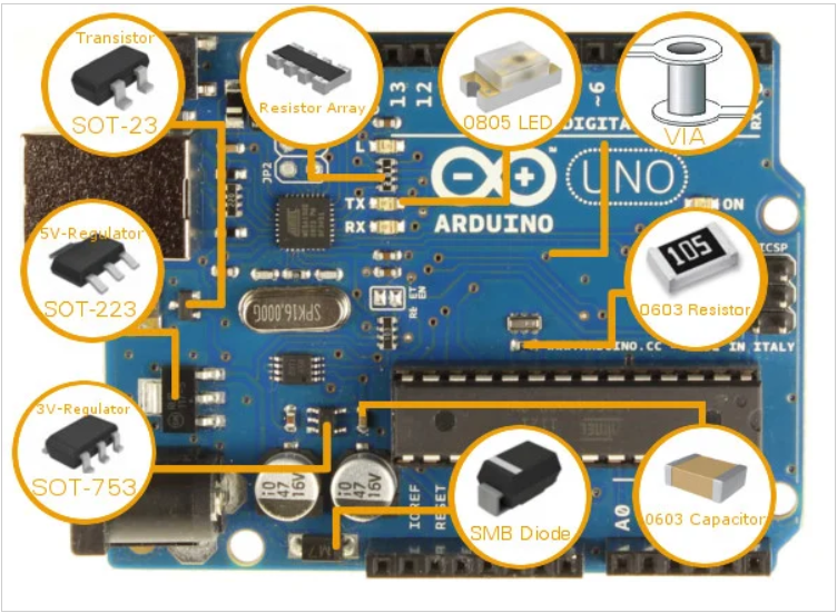
In the table below, you can see a list of some components in the Arduino UNO with their respective package:

Arduino UNO System Overview
Before we can understand the UNO's hardware, we must have a general overview of the system first.
After your code is compiled using Arduino IDE, it should be uploaded to the main microcontroller of the Arduino UNO using a USB connection. Because the main microcontroller doesn’t have a USB transceiver, you need a bridge to convert signals between the serial interface (UART interface) of the microcontroller and the host USB signals.
The bridge in the latest revision is the ATmega16U2, which has a USB transceiver and also a serial interface (UART interface).
To power your Arduino board, you can use the USB as a power source. Another option is to use a DC jack. You may ask, “if I connect both a DC adapter and the USB, which will be the power source?” The answer will be discussed in the “Power Part” section from this article.
To reset your board, you should use a push button in the board. Another source of reset should be every time you open the serial monitor from Arduino IDE.
I redistributed the original Arduino UNO schematic to be more readable below. I advise you to download it and open the PCB and schematic using Eagle CAD while you are reading this article.

Redistributed version of the original Arduino schematic. Click to enlarge.
The Microcontroller
It is important to understand that the Arduino board includes a microcontroller, and this microcontroller is what executes the instructions in your program. If you know this, you won't use the common nonsense phrase "Arduino is a microcontroller" ever again.
The ATmega328 microcontroller is the MCU used in Arduino UNO R3 as a main controller. ATmega328 is an MCU from the AVR family; it is an 8-bit device, which means that its data-bus architecture and internal registers are designed to handle 8 parallel data signals.
ATmega328 has three types of memory:
- Flash memory: 32KB nonvolatile memory. This is used for storing application, which explains why you don't need to upload your application every time you unplug arduino from its power source.
- SRAM memory: 2KB volatile memory. This is used for storing variables used by the application while it's running.
- EEPROM memory: 1KB nonvolatile memory. This can be used to store data that must be available even after the board is powered down and then powered up again.
Let us briefly go over some of this MCU's specs:
Packages:
This MCU is a DIP-28 package, which means that it has 28 pins in the dual in-line package. These pins include power and I/O pins. Most of the pins are multifunctional, which means that the same pin can be used in different modes based on how you configure it in the software. This reduces the necessarpy pin count, because the microcontroller does not require a separate pin for every function. It can also make your design more flexible, because one I/O connection can provide multiple types of functionality.
Other packages of ATmega328 are available like TQFP-32 SMD package (Surface Mount Device).

Two different packages of the ATmega328. Images courtesy of Sparkfun and Wikimedia.
Power:
The MCU accepts supply voltages from 1.8 to 5.5 V. However, there are restrictions on the operating frequency; for example, if you want to use the maximum clock frequency (20 MHz), you need a supply voltage of at least 4.5 V.
Digital I/O:
This MCU has three ports: PORTC, PORTB, and PORTD. All pins of these ports can be used for general-purpose digital I/O or for the alternate functions indicated in the pinout below. For example, PORTC pin0 to pin5 can be ADC inputs instead of digital I/O.
There are also some pins that can be configured as PWM output. These pins are marked with “~” on the Arduino board.
Note: The ATmega168 is almost identical to the ATmega328 and they are pin compatible. The difference is that the ATmega328 has more memory—32KB flash, 1KB EEPROM, and 2KB RAM compared to the ATmega168's 16KB flash, 512 bytes EEPROM, and 1KB RAM.
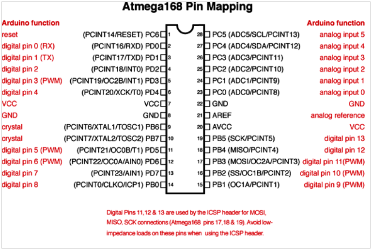
ATmega168 pinout with Arduino labels; the ATmega168 and ATmega328 are pin compatible. Image courtesy of Arduino.
Reading the Rugged Circuits post about protection in Arduino is very useful. You should now be more familiar with the Arduino UNO's electronic design and have a better understanding of its hardware. I hope this helps your design projects in the future!